The TileSystem is the required flexible and compact embedded processing platform.
The concept was finalized during the MARISense project.
TileCube System
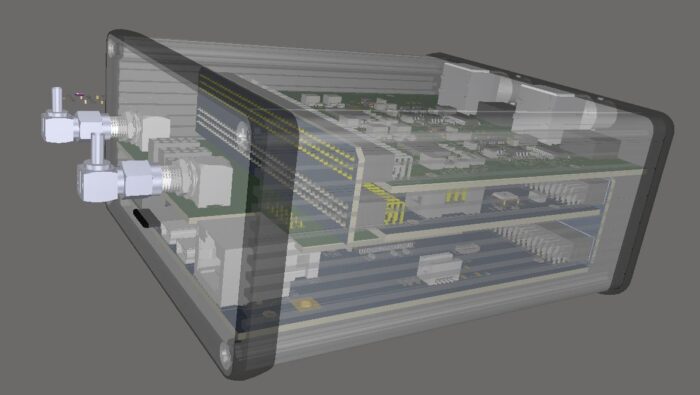
When all the parts of the system came, we were able to check the designed mechanical integration of a multi-board design using the Altium Designer CAD against the actual hardware. Initially, each component was checked that fit properly the mechanical enclosure. This was a preliminary test to verify PCB width and component height that might affect the assembly. Although the backplane boards are missing from the below setup, the HAT and other connectors and protruding pins were checked for potential conflicts.
4-Channel Hydrophone Edge Processing System
Then we added the back/front plane boards to complete and final check the system assembly.
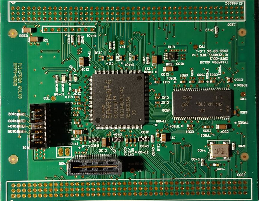
The second element of the TileSystem useful for edge processing is the FPGA board. This board interfaces tightly with the microcontroller of the system using a bus and also with the potential frontends for input or output.
As FPGAs are also hit by the component shortages in the semiconductor market, the design was based on AMD/Xilinx Spartan 6LX9 device, as this was in stock. The fact that the device is in a QFP package (as opposed to BGA) allows a less expensive PCB design with easier debugging, as all pins can be probed.
TileFPGA Board
The board was designed in less than 2 weeks and it came into our lab for verification. In order to test the board, we must connect it to our TileMCU through a backplane, and run the appropriate firmware that will load a valid configuration to the chip. A suitable test design with proper pin constraints was created.
After the assembly of the missing parts, the TileCUBE assembled with the microcontroller and the FPGA.
TileFPGA in Unconfigured State
The initial power-up lit our default LEDs (orange LED lit, means that the FPGA is unconfigured). We had to compile a test design with the updated pin-out from the Perseus CFE board to the TileFPGA. The design was placed at the SDCard. The firmware was adjusted to load this FPGA bitstream, so we can test the MCU and SDRAM interfaces.
FPGA in Configured State
After the FPGA was configured, we tested the Mini-FlexBus interface. We used the debugger to inspect the register area and confirmed the visibility (read operations). Registers were also written to verify that the interface is working as expected. We tested the LED state change (green color seen in the above photo) by changing the relevant bit in a register.
The next phase was to test the internal Block-RAMs. Initially the internal logic did not route the memories to the FlexBus interface (this was a design feature). the values seen in the memory space are 0xFFFF (due to the pull-ups inside the FPGA logic).
Block-RAM Access Enable and Test
Setting the respective enable bit in the control register the memory space can be written and the values are retained. Note that the default memory values seen by the Bus are 0xFFFF, but as soon as we step an instruction after the memory enable bit is set, the debugger refreshes the memory contents that are now zero.
These tests concluded the basic Mini-FlexBus interface and the internal Block-RAM interfaces. In the next post, we will test the SDRAM.
The concept of a flexible and scalable system is a usual requirement for many applications. We initially started this flexibility by integrating MCUs with FPGAs on the same board. These created the initial Perseus Family Platform boards that we used for the development of applications.
Later on, during the MARI-Sense project, it was evident that the form factor should be more compact while features should be more selectable. In that spirit, we created the TileCubeTM System. Toward implementation of the platform, we designed boards for a complete hydrophone system, including microcontroller boards, FPGAs, and analog front-ends.
Due to component shortages, we were forced to design and use existing parts that we had in stock for the boards. Some boards are already designed with higher-performance microcontrollers waiting to have the new parts in hand. The flexibility of the system allows using different MCU boards in a backward-compatible manner.
The first board of the Tile System is the microcontroller. This version is based on Coldfire MCF52258.
CAD Model of TileMCU_CF
Soon the boards arrived to our lab and we started the board bring-up process and testing.
Actual TileMCU_CF Sample
We confirmed the firmware configuration changes to support the new I/O assignment and installed COFILOS to test the system. Soon we had a system working with serial communications, command line interface (CLI), etc.
First Light (Blinking) of Firmware
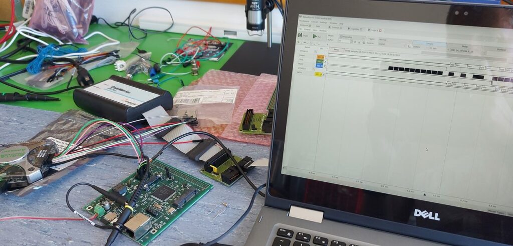
Next steps were to verify the SDCard interface and we tried the first time the Digilent Digital Discovery tool for capturing SPI data.
SDCard SPI Checks
Finally, we confirmed the proper operation of the SDCard and through the CLI we sneaked into the first sector of the device.
SDCard First Sector
Initially, the same board was designed with another microcontroller in mind, but due to component shortages, we had to re-spin the board with Coldfire. It was a fast race to quickly redesign the board, build it and make it work, within our deadlines. This gave us the motivation to complete the rest of the boards with the same speed, so we can see the full system ready and explore the potential of the system.
If you are interested in this platform feel free to contact us.