Photos from Breaking the Surface 2024 Conference

BtS2024 – Press RELEASE

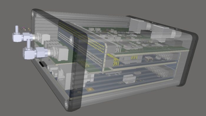
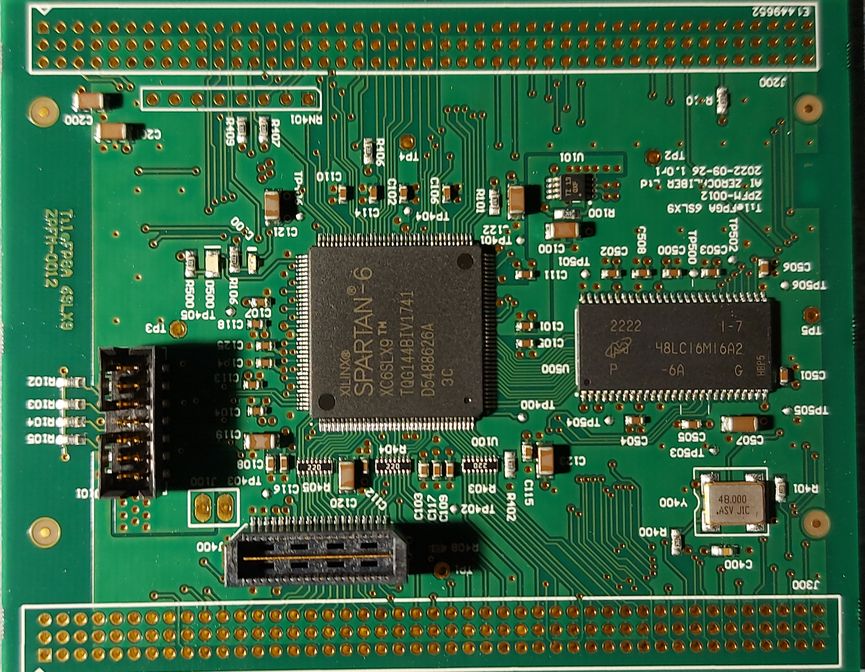
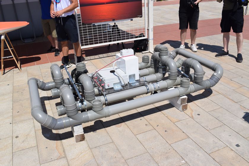
In September 2024 AI Zerocaliber Ltd launched its second-generation power management solution. The product addresses applications for remote sensing, buoys, USVs and other IoT long-term operations that require energy surveillance, conservation or power switching.

Photos from Demo in Breaking the Surface 2024, showing Power Management System
Power Management Demo

Currently, the first generation of our power management products serve in USVs and Buoys in Cyprus for more than two years, supporting the local research community.

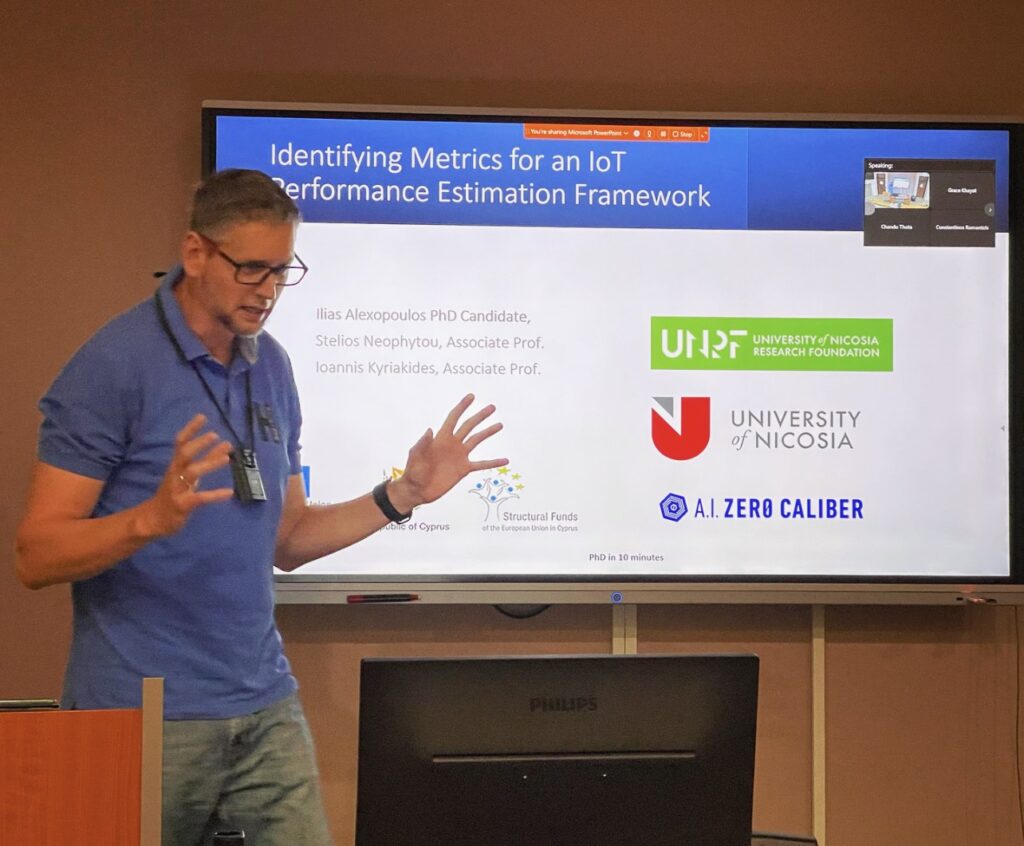
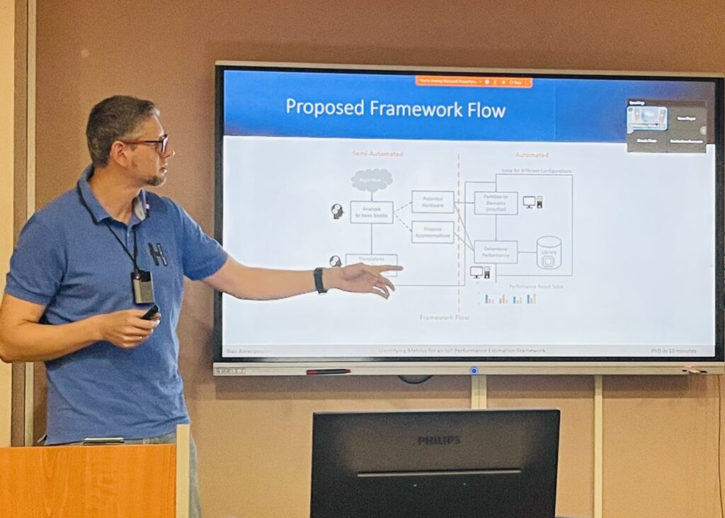
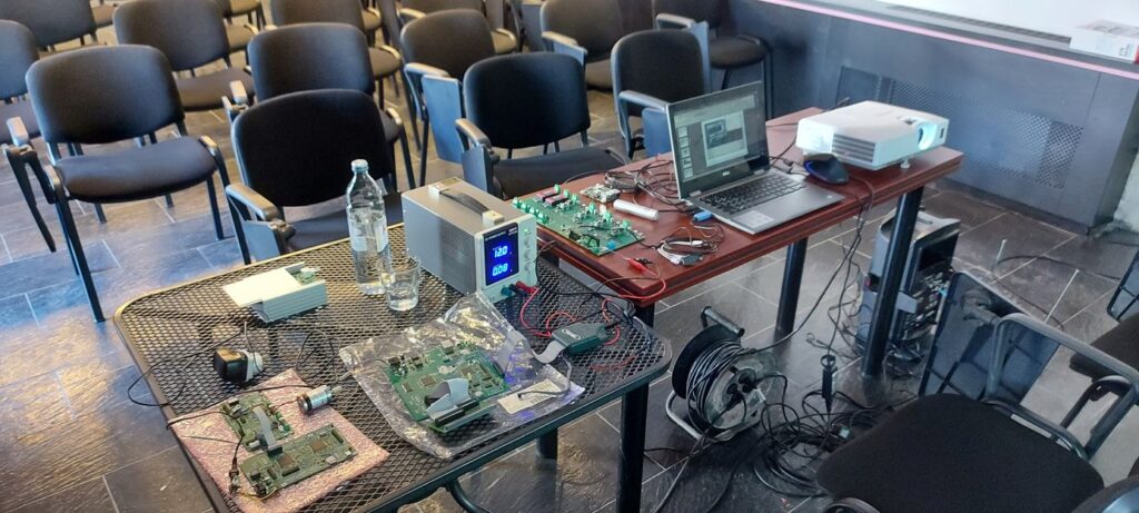
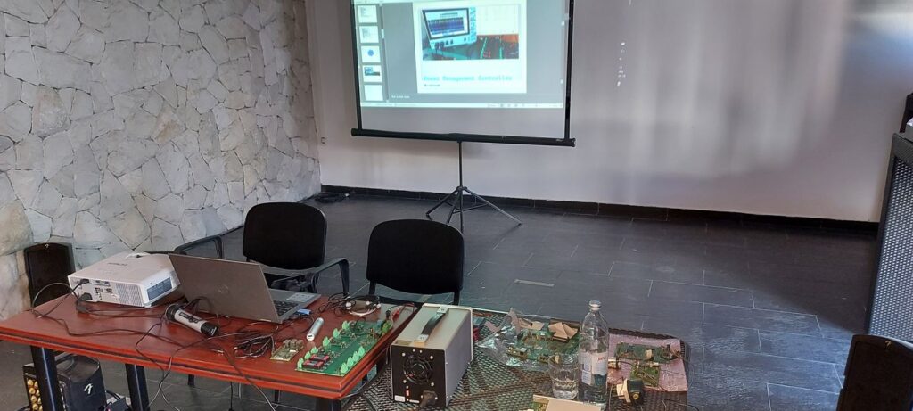
The second generation of the product was demonstrated at Breaking the Surface conference (BtS 2024) this September, where researchers and industry experts had the opportunity to evaluate its potential in respect to robotics and marine applications.

Photos from Breaking the Surface 2024 Conference
Kick-Off BtS 2024

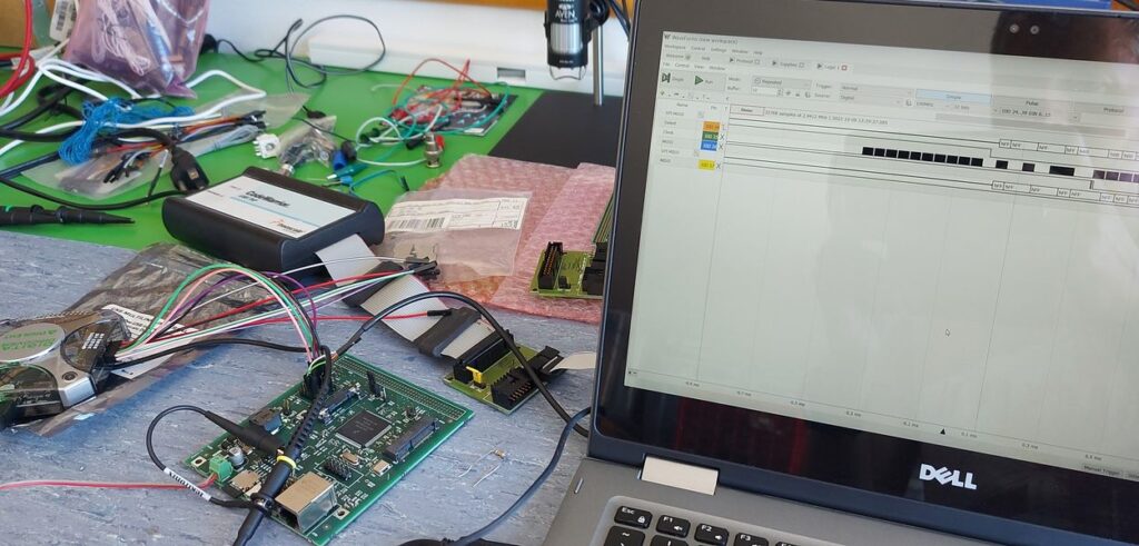
The demonstration showcased our product, and an example web-based dashboard was presented. Discussions were held about its capabilities and configuration options with potential users. The product will be available for orders from February of 2025. Please contact us for more information and details. We will be happy to discuss your needs and provide a solution tailored to your specific application.

Photos from Demo in Breaking the Surface 2024
Photos from Demo in BtS2024

You may see the product page for more details: Power Management V2 – AI ZeroCaliber LTD

Building the TileCube

The TileSystem is the required flexible and compact embedded processing platform.

The concept was finalized during the MARISense project.

TileCube System

When all the parts of the system came, we were able to check the designed mechanical integration of a multi-board design using the Altium Designer CAD against the actual hardware. Initially, each component was checked that fit properly the mechanical enclosure. This was a preliminary test to verify PCB width and component height that might affect the assembly. Although the backplane boards are missing from the below setup, the HAT and other connectors and protruding pins were checked for potential conflicts.

4-Channel Hydrophone Edge Processing System

Then we added the back/front plane boards to complete and final check the system assembly.

Checking FPGA-SDRAM Interface

The next step of the TileFPGA testing is the SDRAM interface.

As you may see in the following video, writing to the SDRAM memory space seems successful, but reading back the data by refreshing the debugger view, shows that the memory is sparsely written (or ghost read).

FPGA SDRAM Failed Access

This usually is an indicator of the clock phase, which can be addressed in the design’s clock generation phase. By adjusting the clock phase, the clock becomes in sync with the signals and hence the SDRAM is operating properly.

This concludes the TileFPGA testing for now. In the next blog the Hydro4 ADC interface will be checked.

PhD in 10 minutes

A few weeks ago Ilias Alexopoulos presented part of his PhD work on IoT performance Estimation.

Engineers involved in developing IoT either remote or not, have to deal with key parameters like power consumption, computation speed, or resources, depending on the cost function of each project.

The presenter making the introduction

The problem is to estimate the best performance according to the key project parameters of an implementation and more specifically of an algorithm with respect to different hardware. Each hardware can offer different kinds of optimizations so the combinations of each implementation involving algorithm variants and hardware optimization is unmanageable.

The framework flow
Presenting the Framework Flow

The work of this research is to establish a framework that can estimate this individual performance and provide guidance to the designer of the best hardware without the need of implementing the algorithms on any platform.

Presenting Conclusion and Challenges
Conclusion and Challenges

It is a long shot to achieve this goal, but research and progress are about challenges. Challenging methods, tools, or our limits to achieve more.

Building the FPGA Board

The second element of the TileSystem useful for edge processing is the FPGA board. This board interfaces tightly with the microcontroller of the system using a bus and also with the potential frontends for input or output.

As FPGAs are also hit by the component shortages in the semiconductor market, the design was based on AMD/Xilinx Spartan 6LX9 device, as this was in stock. The fact that the device is in a QFP package (as opposed to BGA) allows a less expensive PCB design with easier debugging, as all pins can be probed.

TileFPGA Board

The board was designed in less than 2 weeks and it came into our lab for verification. In order to test the board, we must connect it to our TileMCU through a backplane, and run the appropriate firmware that will load a valid configuration to the chip. A suitable test design with proper pin constraints was created.

After the assembly of the missing parts, the TileCUBE assembled with the microcontroller and the FPGA.

TileFPGA in Unconfigured State

The initial power-up lit our default LEDs (orange LED lit, means that the FPGA is unconfigured). We had to compile a test design with the updated pin-out from the Perseus CFE board to the TileFPGA. The design was placed at the SDCard. The firmware was adjusted to load this FPGA bitstream, so we can test the MCU and SDRAM interfaces.

FPGA in Configured State

After the FPGA was configured, we tested the Mini-FlexBus interface. We used the debugger to inspect the register area and confirmed the visibility (read operations). Registers were also written to verify that the interface is working as expected. We tested the LED state change (green color seen in the above photo) by changing the relevant bit in a register.

The next phase was to test the internal Block-RAMs. Initially the internal logic did not route the memories to the FlexBus interface (this was a design feature). the values seen in the memory space are 0xFFFF (due to the pull-ups inside the FPGA logic).

Block-RAM Access Enable and Test

Setting the respective enable bit in the control register the memory space can be written and the values are retained. Note that the default memory values seen by the Bus are 0xFFFF, but as soon as we step an instruction after the memory enable bit is set, the debugger refreshes the memory contents that are now zero.

These tests concluded the basic Mini-FlexBus interface and the internal Block-RAM interfaces. In the next post, we will test the SDRAM.

TileMCU FirmWare

The TileMCU Coldfire version completed its first set of tests, completing the integration of the USB stack from Freescale/NXP to the RTOS.

Using POSIX-style drivers (or any standard way of interfacing) we were able to replace the Serial input of the Command Line Interpreter (CLI) with the USB one.

The code change was a very simple one, replacing just the name of the driver.

Code Excerpt of Selectable Driver

So essentially we define a preprocessor macro with the name of the required driver. As both the USB-CDC and the Serial driver have the same API, they can be interchanged at will.

Here we do this on compile time. Another option would be to mirror both interfaces and have at the same time either USB or Serial I/O. For now, we decided to keep it simple as we have to test the rest of the boards to complete our hydrophone system.

USB Enumeration

At first, the USB enumeration was checked to see if the basics worked. Then we opened with our terminal the respective virtual serial port and start testing the CLI.

CLI Test Example

The CLI was tested to ensure that there were no problems using it and testing some other functions like the SD Card mounting and FAT access.

As we have completed the first phase of testing we can move on to the next boards for testing. We will return back to this board to test the Mini-FlexBus interface with the FPGA.

Building the MCU Board

The concept of a flexible and scalable system is a usual requirement for many applications. We initially started this flexibility by integrating MCUs with FPGAs on the same board. These created the initial Perseus Family Platform boards that we used for the development of applications.

Later on, during the MARI-Sense project, it was evident that the form factor should be more compact while features should be more selectable. In that spirit, we created the TileCubeTM System. Toward implementation of the platform, we designed boards for a complete hydrophone system, including microcontroller boards, FPGAs, and analog front-ends.

Due to component shortages, we were forced to design and use existing parts that we had in stock for the boards. Some boards are already designed with higher-performance microcontrollers waiting to have the new parts in hand. The flexibility of the system allows using different MCU boards in a backward-compatible manner.

The first board of the Tile System is the microcontroller. This version is based on Coldfire MCF52258.

CAD Model of TileMCU_CF

Soon the boards arrived to our lab and we started the board bring-up process and testing.

Actual TileMCU_CF Sample

We confirmed the firmware configuration changes to support the new I/O assignment and installed COFILOS to test the system. Soon we had a system working with serial communications, command line interface (CLI), etc.

First Light (Blinking) of Firmware

Next steps were to verify the SDCard interface and we tried the first time the Digilent Digital Discovery tool for capturing SPI data.

SDCard SPI Checks

Finally, we confirmed the proper operation of the SDCard and through the CLI we sneaked into the first sector of the device.

SDCard First Sector

Initially, the same board was designed with another microcontroller in mind, but due to component shortages, we had to re-spin the board with Coldfire. It was a fast race to quickly redesign the board, build it and make it work, within our deadlines. This gave us the motivation to complete the rest of the boards with the same speed, so we can see the full system ready and explore the potential of the system.

If you are interested in this platform feel free to contact us.

EOC2022 Compact Heterogenous Computing Platforms

Embedded Online Conference 2022

This year we will present how to create heterogeneous embedded platforms using Coldfire or Kinetis microcontrollers and FPGAs. We will touch on some interesting points related to such implementations.

EOC2022 Compact Heterogenous Computing Platforms
Compact Heterogeneous Computing Platforms

We hope that you will enjoy this talk and the small demonstration of integration between MCUs and FPGAs.

Edge Computing for Maritime IoT @BTS

“Breaking The Surface 2021” event was very successful and interesting. Many scientists of all over thw world presented the latest developments in archeology, marine robotics, sensing and other applications.

We were honored to present our maritime IoT platforms and share our knowledge on embedded system design and hardware acceleration.

BTS Tutorial

We discussed things like power management, showcasing the power management board for the MARI-Sense ASV, hardware acceleration, and versatile heterogeneous platforms.

Ready for the Tutorial with all Hardware
Power Management GUI

For more details see the following link.

Tutorial 2 Intro – AI Zerocaliber: Edge Computing for Maritime IoT – Breaking the Surface (fer.hr)

EMD2021: Smart-Float

European Maritime Day in Cyprus 2021

In Larnaca, 17-21 June 2021, there was this great event, where we had the opportunity to show our latest developments for the MARI-Sense project in collaboration with CMMI.

On Sunday 21 of June, at Europe Square CMMI and MARI-Sense exhibited various vehicles for maritime applications.

The underwater remote controlled robotic vehicle (ROV) has the capability to provide underwater images or use manipulators to perform delicate actions as required for research or other applications.

EMD2021: CMMI ROV Exhibit
Front view of the CMMI’s Robotic Underwater Vehicle

A smart-boat is also developed named “Kerkouros” from the ancient Cyprus ship with oars. “Kerkouros” is under development with the ultimate goal to be an autonomous surface vehicle; a challenging task for the development team.

EMD2021: Smart-Boat "Kerkouros" Exhibit
Prototype of Autonomous Smart Boat Developed at CMMI

For helping development efforts for the MARI-Sense project another platform was exhibited, the Smart-Float. The Smart Float will be used as a technology evaluation platform, where different sensors will be mounted and tested along with radio links, like WiFi, LoRa, thrusters, maneuverability, or other technologies and embedded systems. This platform will help improve the know-how of the team and will lead to new improved models. The main advantage of this platform is its low-cost and large transport capacity (more than 20Kgr net for payload). The team is already thinking of other potential applications where this platform can be used effectively. AI Zerocaliber Ltd is involved with this platform from the concept phases till now, helping with the hull and system design, and specific embedded components.

EMD2021: Smart-Float
Smart-Float Platform Shown During EMD-2021 Event

For more information on the MARI-Sense project you may check the project’s website.

MARI-Sens Logo